HL1 Quarter Turn Actuator
Overview
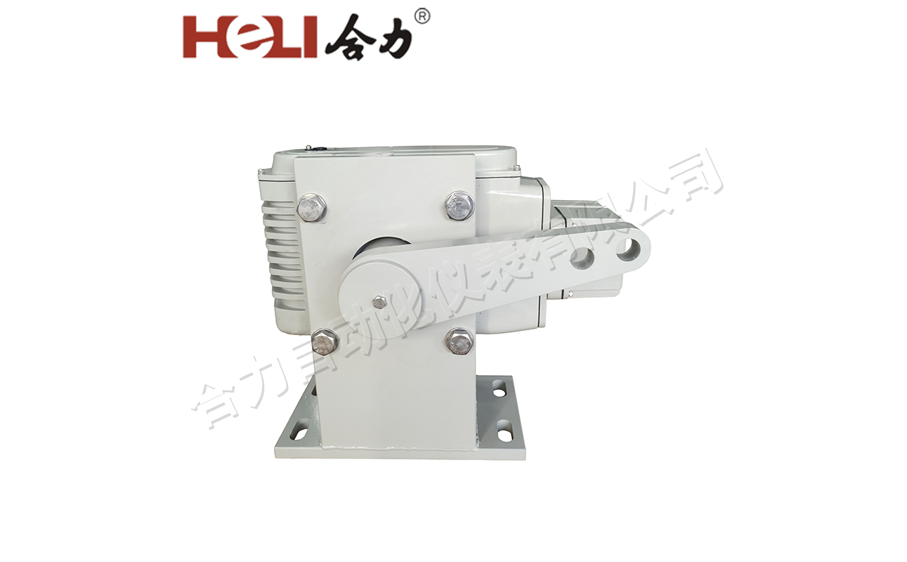
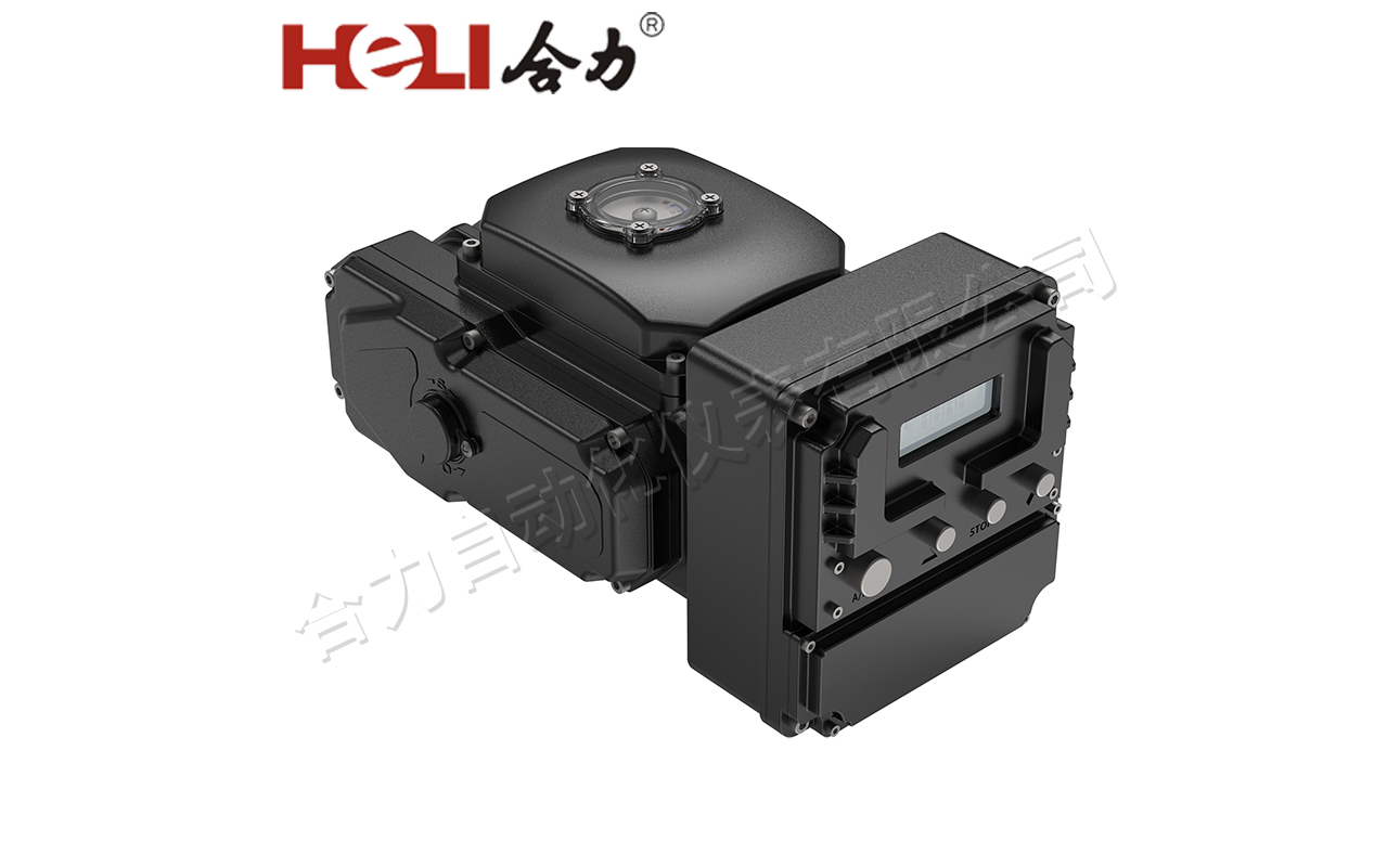
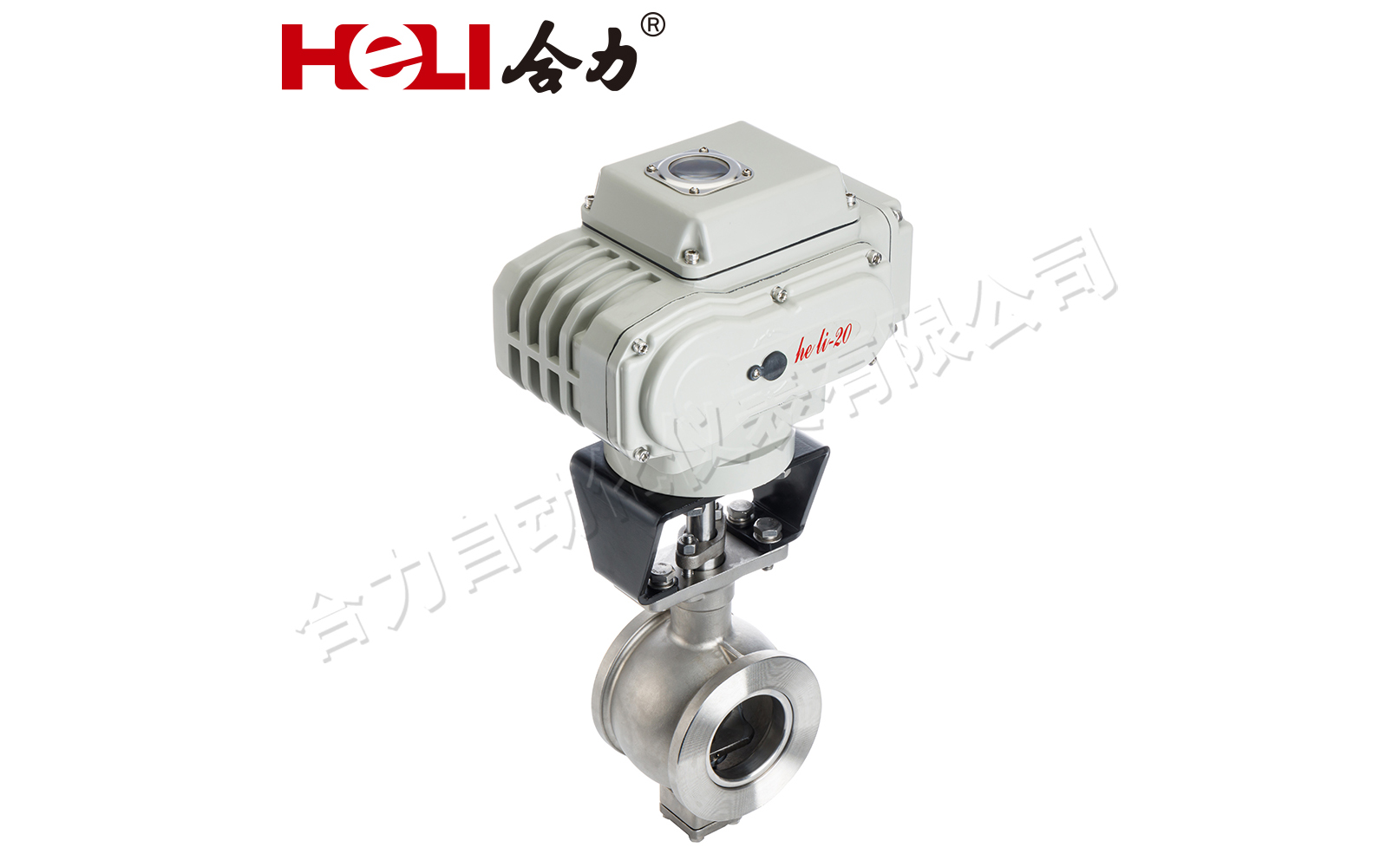
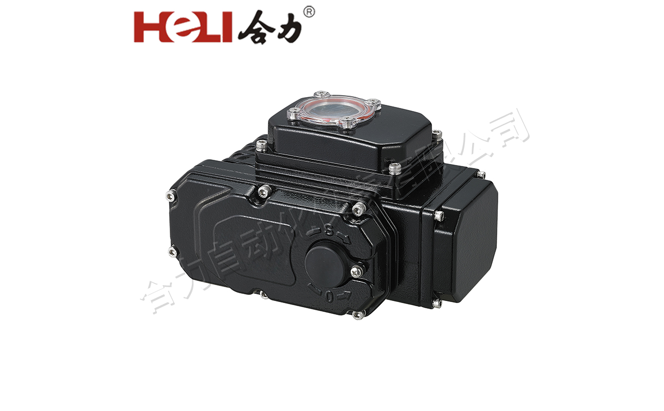
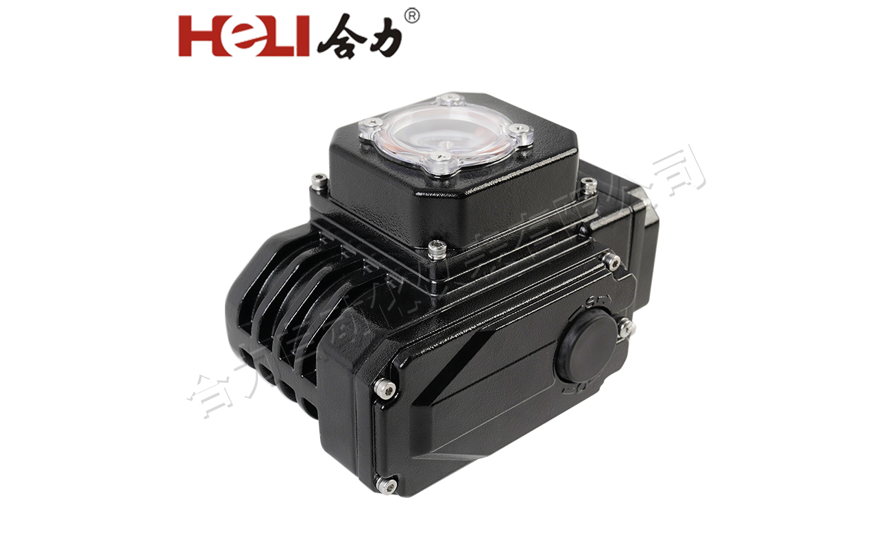
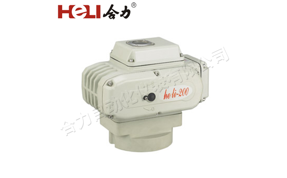
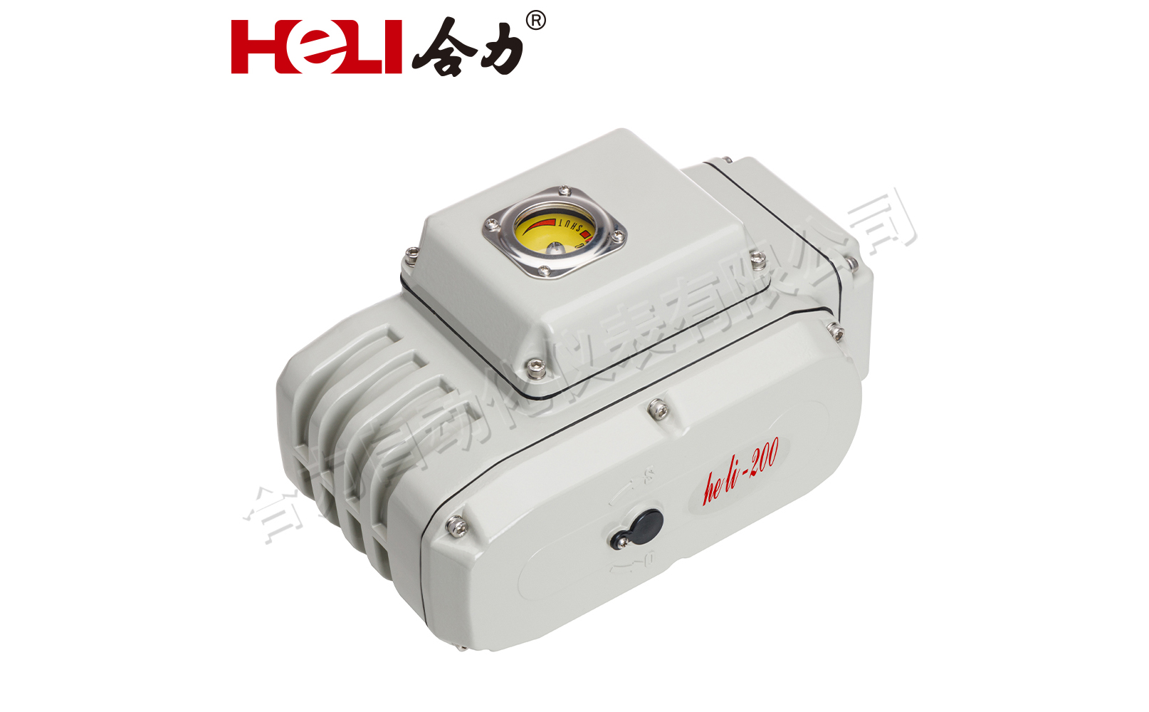
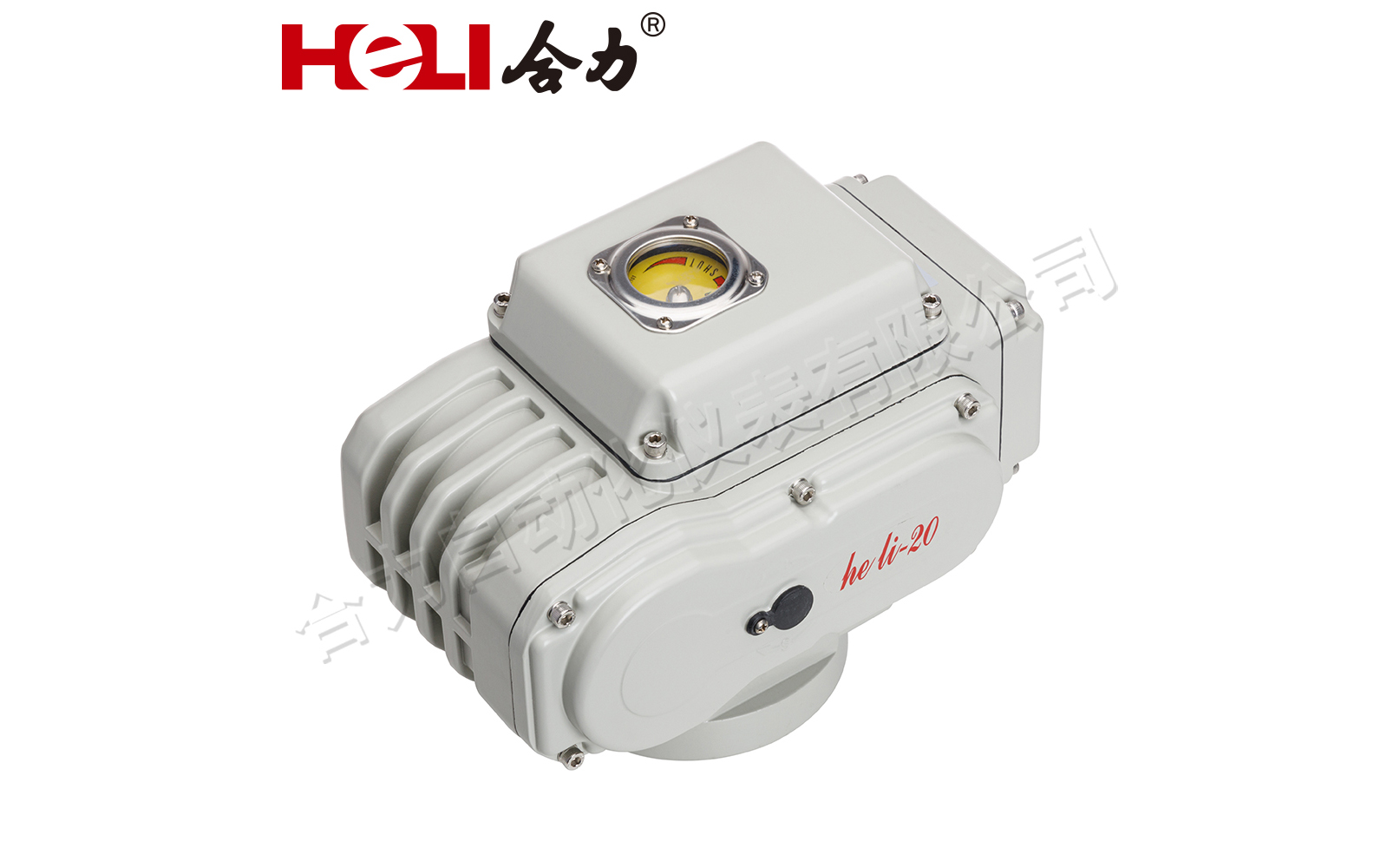
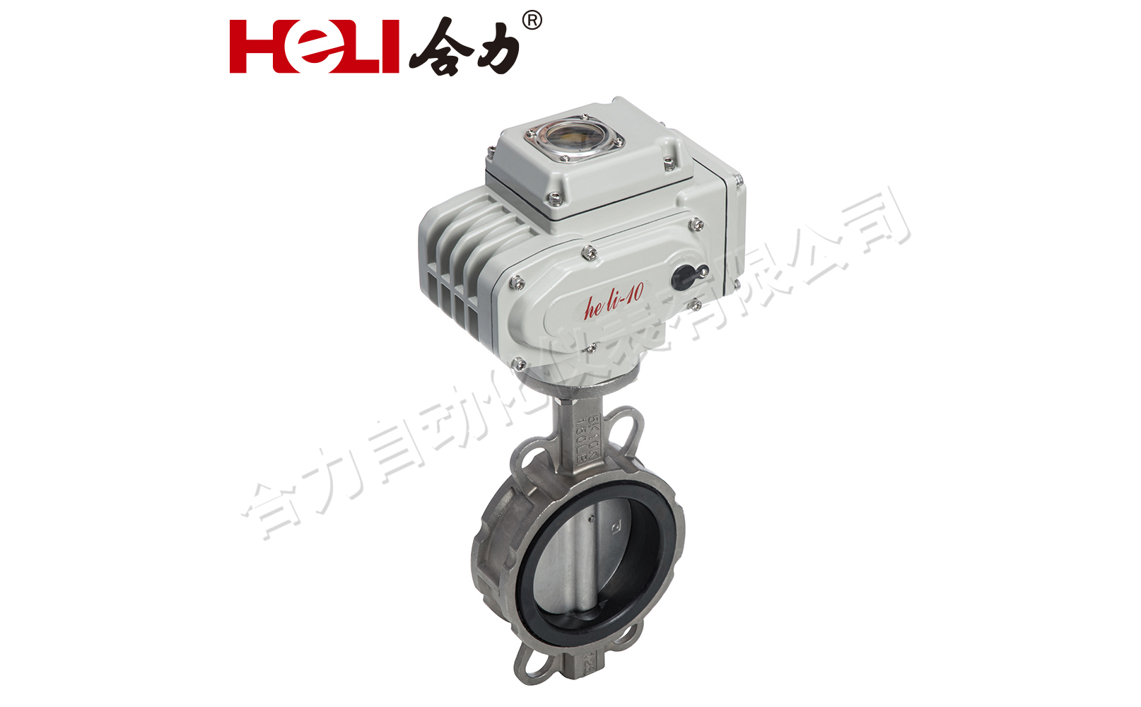
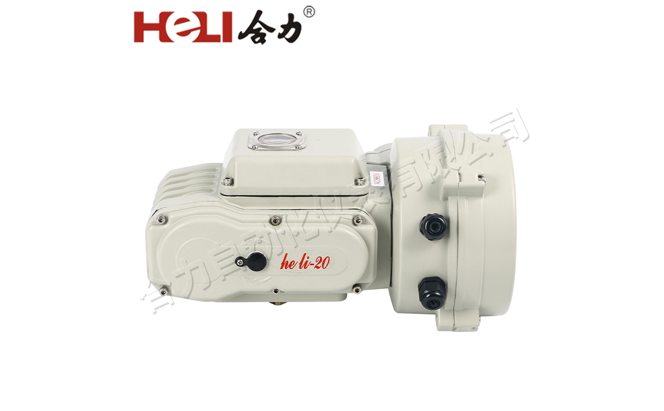
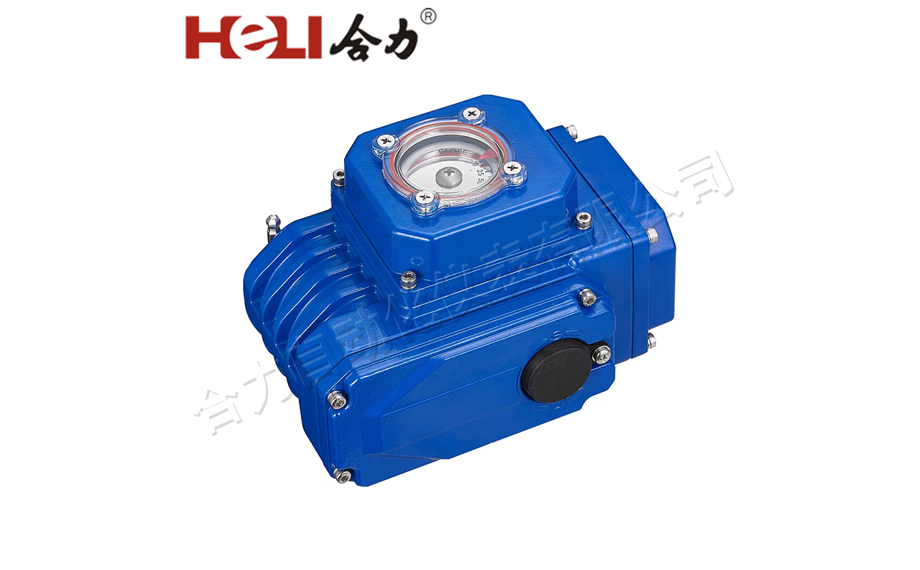
The HL Series electric actuators are compact excellent weather resistance and shock resistance.When the actuator is powered off,the self-locking transmission mechanism ensures that the valve position unchanged,with electrical and mechanical double limits to prevent overdrive.Removable drive adapter sleeve,ISO5211 standard flange,suitable for butterfly valve,ball valve,plug valve and other valves,and suitable for various working conditions and voltage levels.
Features
Torque:50NM-6000NM
Seperate wiring space,avoid misoperating
Mini size,easy to install
90°rotary,open and close quickly
Simple mechanical structure,self locking,high driving accuracy
Various control and feedback signal can be choosen
IP67,IP68 protection
Heater space as standard,prevent condensation
Modular design for easy disassembly and maintenance
Specification
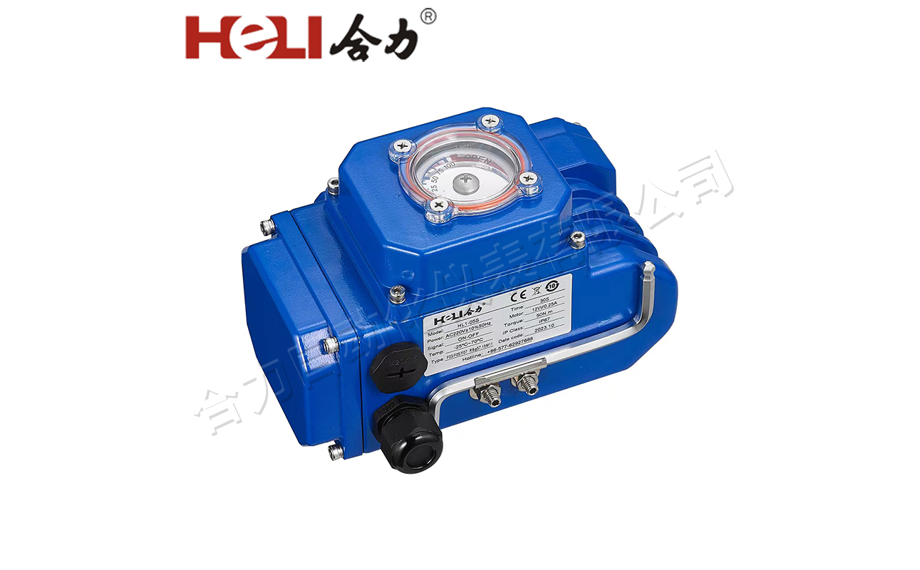
Torque | 50-6000Nm |
Power supply | AC24V/220V/380V..(±10%)DC12V/24V/48V.(±10%) |
Frequency | 50/60Hz(±5%) |
Rotary angle | 0-90° |
Travel/assistant switch | 2xSPDT,250VAC 5A |
Cable gland | On off type:1-M20x1.5 |
Modulating type:2-M20x1.5 | |
Flange | ISO5211 |
Indicator | Indication arrow/3D dome indicator |
Manual | Allen key (hand wheel as optional) |
Protection class | IP67(IP68 as optional,15meter-72hour) |
Working conditions | Temperature:-25℃~70℃ (Optional:-40℃~70℃) |
Humidity:≤95% | |
Anti-condensation | Heater |
Overheat protection | Motor overheat protection,starting temperature:125℃(±5%) |
Power failure state | Last position |
Signal failure state | 4-20mA/2-10V full open/close(factory defaults is signal failure for last position) |
0-10V:full close | |
Duty cycle | On off type:S2-15 Min;Modulating type:S4-50% |
Overtorque | Optional |
Motor | Squirrel cage induction motor,class F(class H as optional) |
Noisy | ≤70dB(A)-1M |
Mechanical Data
Model | Torque (N.m) | Adapter (mm) | Flange ISO5211 | Weight (KG) |
HL1-05 | 50 | 14*14 | F03/F05/F07 | 3 |
HL2-10 | 100 | 17*17 | F05/F07 | 4 |
HL2-16 | 160 | 17*17 | F05/F07 | 4.5 |
HL3-25 | 250 | 22*22 | F07/F10/F12 | 9 |
HL3-40 | 400 | 22*22 | F07/F10/F12 | 9.5 |
HL3-60 | 600 | 27*27 | F07/F10/F12 | 9.5 |
HL4-100 | 1000 | 27*27 | F12 or F10/F14 | 14.5 |
HL4-160 | 1600 | 36*36 | F12 or F10/F14 | 14.5 |
HL4-200 | 2000 | 36*36 | F12 or F10/F14 | 14.5 |
HL5-250 | 2500 | 36*36 | F14 or F12/F16 | 24.9 |
HL5-300 | 3000 | 36*36 | F14 or F12/F16 | 24.9 |
HL6-400 | 4000 | 46*46 | F16 or F25 | 43.5 |
HL6-600 | 6000 | 46*46 | F16 or F25 | 57.1 |
Electrical Performance Data
1PH
Model | Torque (N.m) | Time (Sec/0-90°) | Motor power (W) | 110VAC Current (A) | 220VAC Current (A) | ||
Running | Blocking | Running | Blocking | ||||
HL1-05 | 50 | 30 | 10 | 0.45 | 0.67 | 0.24 | 0.31 |
HL2-10 | 100 | 20 | 30 | 0.65 | 0.96 | 0.35 | 0.45 |
HL2-16 | 160 | 30 | 30 | 0.65 | 0.96 | 0.35 | 0.45 |
HL3-25 | 250 | 30 | 40 | 0.72 | 1.41 | 0.38 | 0.71 |
HL3-40 | 400 | 30 | 60 | 1.0 | 1.74 | 0.5 | 0.95 |
HL3-60 | 600 | 30 | 90 | 1.5 | 2.62 | 0.75 | 1.48 |
HL4-100 | 1000 | 30 | 150 | 3 | 5.92 | 1.5 | 2.87 |
HL4-160 | 1600 | 50 | 150 | 3 | 5.92 | 1.5 | 2.87 |
HL4-200 | 2000 | 60 | 150 | 3 | 5.92 | 1.5 | 2.87 |
HL5-250 | 2500 | 50 | 200 | 3.9 | 7.24 | 1.9 | 3.05 |
HL5-300 | 3000 | 60 | 200 | 3.9 | 7.24 | 1.9 | 3.05 |
HL6-400 | 4000 | 100 | 200 | 4.1 | 7.13 | 2.1 | 3.17 |
HL6-600 | 6000 | 150 | 200 | 4.1 | 7.13 | 2.1 | 3.17 |
DC
Model | Torque (N.m) | Time (Sec/0-90°) | Motor power (W) | 110VAC Current (A) | 220VAC Current (A) | ||
Running | Blocking | Running | Blocking | ||||
HL1-05 | 50 | 20 | 15 | 1.1 | 2.6 | 0.7 | 1.5 |
HL2-10 | 100 | 15 | 25 | 1.7 | 2.7 | 0.8 | 1.6 |
HL2-16 | 160 | 20 | 25 | 1.7 | 2.7 | 0.9 | 1.6 |
HL3-25 | 250 | 15 | 40 | 4.0 | 6.5 | 2.1 | 5.3 |
HL3-40 | 400 | 15 | 60 | 6.8 | 10.3 | 3.6 | 5.3 |
HL3-60 | 600 | 15 | 90 | 9.5 | 15.8 | 4.6 | 6.5 |
HL4-100 | 1000 | 30 | 90 | 9.5 | 16.4 | 4.6 | 6.5 |
HL4-160 | 1600 | 30 | 120 | 15 | 27 | 8 | 10.3 |
HL4-200 | 2000 | 30 | 150 | 18 | 27 | 10 | 15.8 |
3PH
Model | Torque (N.m) | Time (Sec/0-90°) | Motor power (W) | 110VAC Current (A) | 220VAC Current (A) | ||
Running | Blocking | Running | Blocking | ||||
HL1-05 | 50 | 30 | 10 | 0.11 | 0.13 | 0.1 | 0.12 |
HL2-10 | 100 | 20 | 30 | 0.12 | 0.17 | 0.11 | 0.13 |
HL2-16 | 160 | 30 | 30 | 0.13 | 0.17 | 0.12 | 0.13 |
HL3-25 | 250 | 30 | 40 | 0.18 | 0.25 | 0.17 | 0.23 |
HL3-40 | 400 | 30 | 60 | 0.25 | 0.49 | 0.23 | 0.47 |
HL3-60 | 600 | 30 | 90 | 0.3 | 0.49 | 0.27 | 0.47 |
HL4-100 | 1000 | 30 | 150 | 0.67 | 1.31 | 0.59 | 1.11 |
HL4-160 | 1600 | 50 | 150 | 0.67 | 1.31 | 0.59 | 1.11 |
HL4-200 | 2000 | 60 | 150 | 0.67 | 1.31 | 0.59 | 1.11 |
HL5-250 | 2500 | 50 | 200 | 0.9 | 1.76 | 0.79 | 1.54 |
HL5-300 | 3000 | 60 | 200 | 0.9 | 1.76 | 0.79 | 1.54 |
HL6-400 | 4000 | 100 | 200 | 0.9 | 1.76 | 0.79 | 1.54 |
HL6-600 | 6000 | 150 | 200 | 0.9 | 1.76 | 0.79 | 1.54 |
Dimension Diagram

Model | A | B | C | D | E | H | T | G | ΦI | J |
HL1-05 | 115 | 26 | 71 | 180 | 87 | 121 | 26 | 9*9 11*11 14*14 | 36 50 70 | 4-M5 4-M6 4-M8 |
HL2-10 | 125 | 26 | 83 | 220 | 105 | 140 | 35 | 11*11 14*14 17*17 | 50 70 | 4-M6 4-M8 |
HL2-16 | 125 | 26 | 83 | 220 | 105 | 140 | 35 | |||
HL3-25 | 168 | 26 | 104 | 294 | 140 | 160 | 45 | 17*17 22*22 27*27 | 70 102 125 | 4-M8 4-M10 4-M12 |
HL3-40 | 168 | 26 | 104 | 294 | 140 | 160 | 45 | |||
HL3-60 | 168 | 26 | 104 | 294 | 140 | 160 | 45 | |||
HL4-100 | 193 | 26 | 124 | 315 | 145 | 195 | 50 | 22*22 27*27 36*36 | 125 102 140 | 4-M12 4-M10 4-M16 |
HL4-160 | 193 | 26 | 124 | 315 | 145 | 195 | 50 | |||
HL4-200 | 193 | 26 | 124 | 315 | 145 | 195 | 50 | |||
HL5-250 | 242 | 26 | 148 | 341 | 150 | 266 | 61 | 27*27 36*36 | 140 125 165 | 4-M16 4-M12 4-M20 |
HL5-300 | 242 | 26 | 148 | 341 | 150 | 266 | 61 | |||
HL6-400 | 266 | / | 155 | 439 | 189 | 309 | 82 | 36*36 46*46 | 165 254 | 4-M20 8-M16 |
HL6-600 | 266 | / | 155 | 439 | 189 | 309 | 82 |
Dimension Diagram

Model | A | B | C | D | E | H | T | G | ΦI | J |
HL1-05 | 144 | 26 | 70.5 | 236 | 87 | 177 | 26 | 9*9 11*11 14*14 | 36 50 70 | 4-M5 4-M6 4-M8 |
HL2-10 | 151 | 26 | 82.5 | 275 | 105 | 178 | 35 | 11*11 14*14 17*17 | 50 70 | 4-M6 4-M8 |
HL2-16 | 151 | 26 | 82.5 | 275 | 105 | 178 | 35 | |||
HL3-25 | 176 | 26 | 104 | 336 | 140 | 197 | 45 | 17*17 22*22 27*27 | 70 102 125 | 4-M8 4-M10 4-M12 |
HL3-40 | 176 | 26 | 104 | 336 | 140 | 197 | 45 | |||
HL3-60 | 176 | 26 | 104 | 336 | 140 | 197 | 45 | |||
HL4-100 | 210 | 26 | 124 | 359 | 145 | 202 | 50 | 22*22 27*27 36*36 | 125 102 140 | 4-M12 4-M10 4-M16 |
HL4-160 | 210 | 26 | 124 | 359 | 145 | 202 | 50 | |||
HL4-200 | 210 | 26 | 124 | 359 | 145 | 202 | 50 | |||
HL5-250 | 250 | 26 | 147.5 | 422 | 150 | 266 | 61 | 27*27 36*36 | 140 125 165 | 4-M16 4-M12 4-M20 |
HL5-300 | 250 | 26 | 147.5 | 422 | 150 | 266 | 61 | |||
HL6-400 | 266 | 26 | 155 | 515 | 189 | 309 | 82 | 36*36 46*46 | 165 254 | 4-M20 8-M16 |
HL6-600 | 266 | 26 | 155 | 515 | 189 | 309 | 82 |
Wiring Diagram
| S TYPE:Basic on-off(1PH) |
Terminal wiring instructions: 1.Terminal 1 is connected to the power supply neutral line. 2.When the power supply phase line is connected to terminal 2,it operates in the "open"position.It stops when the OLS activates. and terminal 2 connects with terminal 4. 3.When the power supply phase line is connected to terminal 3,it operates in the "closed"position.It stops when the CLS activates,and terminal 3 connects with terminal 5. 4.Terminal 7 is the common terminal for the passive signal contact.When the "open"position is reached,it connects to terminal 8,and when the "closed"position is reached,connects to terminal 9 5.Terminal 10 is for the heater. 6.Terminal 8 is for the Potentiometer Wiper. 7.Terminal A is the low end of the potentiometer.The resistance between terminals A and B increases when running in the "open" direction 8.Terminal C is the high end of the potentiometer.The resistance between terminals B and C decreases when running in the "open"direction. Note: 1.Two or more electric devices should not be connected in parallel,as this may cause the switch to malfunction or the motor to overheat 2.The open/close valve signal for the passive contact is for indication purposes only and is triggered approximately 3 seconds before the limit switch. | |
| A TYPE:Basic modulating type(1 PH) |
1.Connect the 'N'terminal of the "Power"input to the neutral line,and the 'L"terminal to the phase line. 2.Connect the "+terminal of the "IN'input to the positive end of the input signal,and the "-terminal to the negative end of the input signal. 3.Connect the "+"terminal of the "OUT'output to the positive end of the output signal,and the"-"terminal to the negative end of the output signal. 4.The "Heater"terminal is for the heating dehumidifier. Note: The open/close valve signal for the passive contact is for indication purposes only and is triggered approximately 3 seconds before the limit switch. | |
| S TYPE:Basic on-off type(3 PH) |
Terminal Wiring Instructions: 1.Terminals 1,2,and 3 are connected to the 3 PH power supply after the phase-reversal circuit. 2.Terminal 4 is the common terminal for the control circuit. 3.Terminal 5 is for "open"operation control.After the limit switch OLS activates,terminal 5 disconnects from terminal 4 4.Terminal 6 is for "close"operation control.After the limit switch CLS activates,terminal 6 disconnects from terminal 4. 5.When the "open"operation reaches its position,it connects to terminal 8.Terminal 7 is the common terminal for the passive signal contact,connecting to terminal 8 when "open"and to terminal 9 when "close. 6.Terminal 10 is for the heater. 7.Terminal B is for the Potentiometer Wiper. 8.Terminal A is the low end of the potentiometer,and the resistance between terminals A and B increases when running in the "open"direction. 9.Terminal c is the high end of the potentiometer,and the resistance between terminals B and C decreases when running in the open"direction. Note: 1.For 3 PH power supply,make sure the phase sequence is correct during initial setup to ensure the limit switches can control the motor's opening and closing.Incorrect phase sequence may lead to loss of control or damage to the motor. 2.The open/close valve signal for the passive contact is for indication purposes only and is triggered approximately 3 before the limit switch. | |
| S TYPE:Basic on-off(DC) |
1.When terminal 1 is connected to the positive pole of the power supply and terminal 2 to the negative pole,the actuator operates in the "open"direction.It stops when the travel switch OLS is triggered,and terminal 1 is connected to terminal 3. 2.When terminal 1 is connected to the negative pole of the power supply and terminal 2 to the positive pole,the actuator operates in the "close"direction.It stops when the travel switch CLS is triggered,and terminal 2 is connected to terminal 4 3.Terminal 6 is the common terminal of the passive signal contacts. It connects to terminal 7 when the actuator fully opens and to terminal 8 when it fully closes. 4.Terminals 9 and 10 are for heater 5.Terminal B is the potentiometer wiper. 6.Terminal A is the low end of the potentiometer.The resistance between terminals A and B increases as the actuator moves in the "open"direction. 7.Terminal C is the high end of the potentiometer.The resistance between terminals B and C decreases as the actuator moves in the "open"direction. Note: 1.The valve opening/closing signals from the passive contacts are for indication purposes only and are triggered approximately 3 before the limit switch. | |
| A TYPE:Basic modulating type(DC) |
Wiring Instructions: 1.The "-"terminal is connected to the negative terminal of the power supply.The "+"terminal of the "Power"input terminal is connected to the positive terminal of the power supply. 2.The "+"terminal of the "IN"terminal is connected to the positive terminal of the input signal,and the "-terminal is connected to the negative terminal of the input signal. 3.The "+terminal of the "OUT"terminal is connected to the positive terminal of the output signal,and the "-terminal is connected to the negative terminal of the output signal. 4.The "Heater"terminal is for the Heater. Note: 1.The open/close signal for the passive contact is for indication purposes only and is triggered approximately 3 before the limit switch. |
Note:The wiring inside the frame represents the internal connections of the electric actuator.the right part is for user reference when wiring.Do not connect the power lines of two or more electric actuators in parallel;do not use the same contact point to control two or more actuators,as this may lead to malfunction or motor overheating
Kind Reminder:Standard wiring diagrams or diagrams for other special functions are attached inside the wiring cover of the product.

Explain:
1.The factory setting for "ESD"is SP.The emergency stop can be set by the user to either emergency valve opening or emergency valve closing as needed.
2.In the advanced settings menu, set the remote control mode CC to 'H'for switch control.
3.In the advanced settings menu, set the remote control mode CC to 'C'for analog 4-20mA control.
 Chat Oline